Building a DIY smart home in India is not as easy as getting a bunch of smart plugs & bulbs. This is blog is a first in the series of my journey to convert my “dumb” home to a “smart” home located in India in true DIY fashion using custom built hardware, software & opensource home automation software.
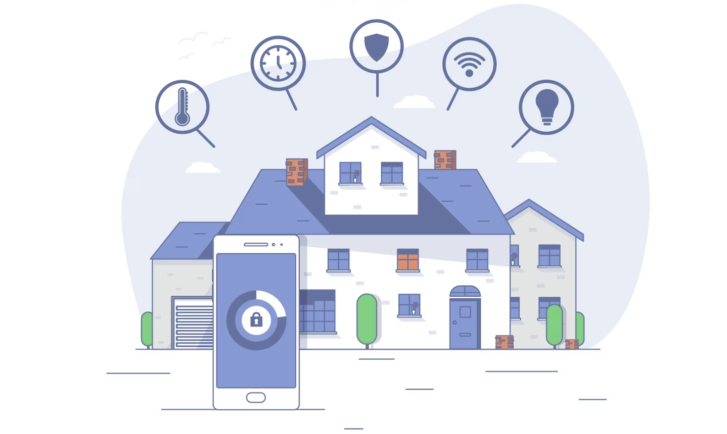
A smart home lets you automate a lot of things in your house based on “states”, these states are derived from sensors or other inputs such as someone being in a room or a door in open state for a while. It also lets you automate things based on time of day.
A smart home is more than a luxury, it frees you up from a lot of repetitive tasks and also improves the peace of mind factor. Being able to control your lights, HVAC & other hosehold systems through your voice / switches or based on rules will open up a lot of possibilties which I never thought about.
Introduction / Why DIY
You can definitely use off-the-shelf smart products such as smart bulbs and smart switches to implement some level of smartness in your home. I have done the same earlier when I was living with my parents & its still working relatively fine.
The problems with off-the-shelf parts are many, the critical one being the need to be connected to the internet all the time to work correctly - about 90% of all the smart home products are just whitelabelled Tuya devices & Tuya isn’t known for privacy & security. Even big brands are partnering with Tuya to come up with smart home products with a re-skinned app. Problem with Tuya is not just security, it needs an active internet connection and most of these devices are very buggy - dropping wifi connection, getting reset randomly, schedules not working reliably sometimes etc. Most of these issues were fixed after I started using the devices for some time, which means they were doing OTA, slightly scary because you don’t have full control over what gets installed as part of OTA on a device that you own, connected to your wifi & hooked up to mains!
Tuya devices were based on the ESP8266 platform up until recently and you could flash a custom firmware such as Tasmota or EPSHome. A custom firware will give you full control of the device & will also cut the ties with chinese servers. Tuya wasn’t liking the idea and switched to a custom module, making it harder to flash a custom firmware but it is still doable.
Phillips and others do have smart home solutions, but are limited with absurd pricing.
When we decided to build a new home, I wanted it to be “smart” & never wanted to use off the shelf smart home products. I decided to build my own hardware and software because it is fun and will give me full control over what happens.
Software / Hardware
There are a lot of options when it comes to Open Source home automation currently. If you don’t want to go via the Open Source / full DIY route, there are platforms like Apple Home Kit & Samsung SmartThings that support offline control, however with a limited feature set. If your internet is down, your lights might not turn on at sun set. Another issue with these devices are the need for specific devices, now that Matter/Thread protocols are becoming popular, it might be possible to mix and match devices in future.
I’ve been using Home Assistant since a few years and it is the platform of choice for many building a smart home. It is backed by a very active community and supports a lot of devices out of the box.
On a high level, my smart home setup looks like the following:
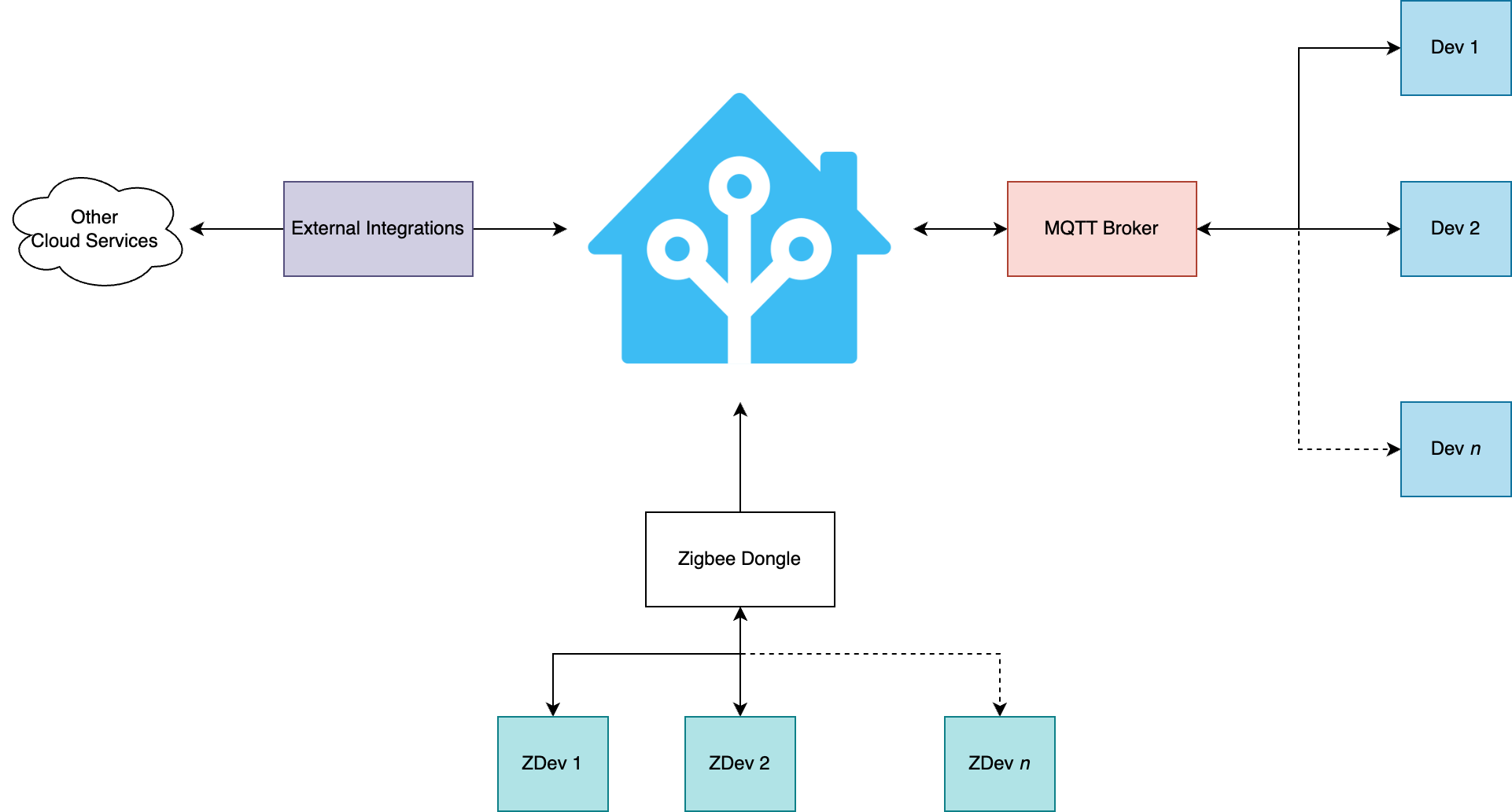
The core of the system is Home Assistant running on a Raspberry Pi 3B using USB boot. An instnace of Mosquitto MQTT broker is running as a service within the home assistant OS, which is the backbone of the operations. Majority of the devices are communicating via MQTT.
This includes a bunch of custom devices that I’ve designed and built running Tasmota firmware plus a bunch of sensors relaying environmental data.
Then there is a separate Zigbee network of devices that communicate with the Home Assistant instance through a Zigbee dongle. I have a bunch of Zigbee devices in my home currently - door/window sensors, motion sensors, smart buttons and weather sensors.
The beauty of Home Assistant is the ability to mix & match different devices/protocols and systems to create a truly automated setup.
Hardware
Instead of going with an off the shelf module, I designed my own - main reason behind this is the requirements I had in mind. Main hardware requirements were as follows:
- Must support offline control
- Must be small enough to fit within a wall panel box
- Should support atleast 6 inputs and 6 outputs
- Should be silent - no relay, solid state control
- Should be repairable
Sonoff and Shelly had a few modules that check some of the boxes at the time, but not all. The custom design will provide the flexibilty I need, but since this is a critical piece of equipment, testing & validation is very very important. Its not ideal if the light doesn’t work when you want to or the fan keeps on running without a way to turn it off!
Design
I’ve started the work on my Smart Home as soon as we layed the first layer of bricks for my new home. The tests that are mentioned below are done at my parents place where I was living at the time.
Hardware design is hard, playing with mains voltage just adds on to the fun. I decided to go with a solid state relay based load control because clicking relays are not that great - from a maintenance perspective and from an overall experience perspective. Controlloing inductive loads such as fans will wear out the relays quickly due to arcing, a solenoid being in an energized state for a long time is not that great either.
The micro controller of choice was ESP32 due to its performance/cost benefits & the availability of proven custom firmware, I’ve decided to use Tasmota here because reinventing the wheel in this case is trivial.
The hardware is based on the following:
- ESP32 Module
- BTA12 Triac
- MOC3023 Optoisolator / Triac Driver
Circuit was designed using EasyEDA & manufactured using a local PCB manufacturer in India.
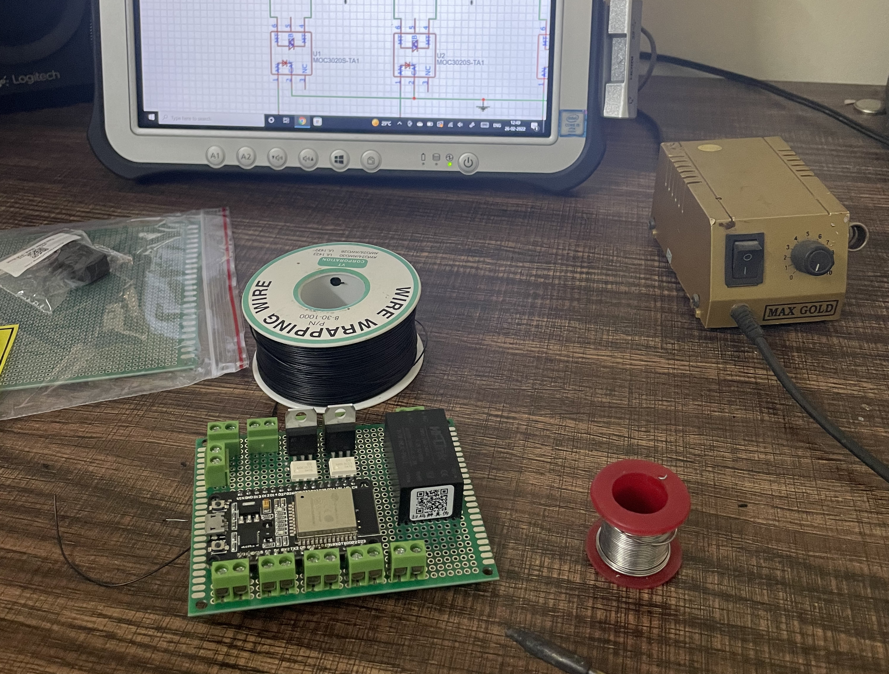
Iteration #1
This design was a proof of concept, it was built using a perf board and an ESP32 DevKit along with the necessary triac circuit. This PoC was kept running for about 3 months within a wall switch board to test the real world performance. It was connected to 3 loads - 1 fan, 2 lights, 4 switches were also connected to the module. Total connected load was around 350W
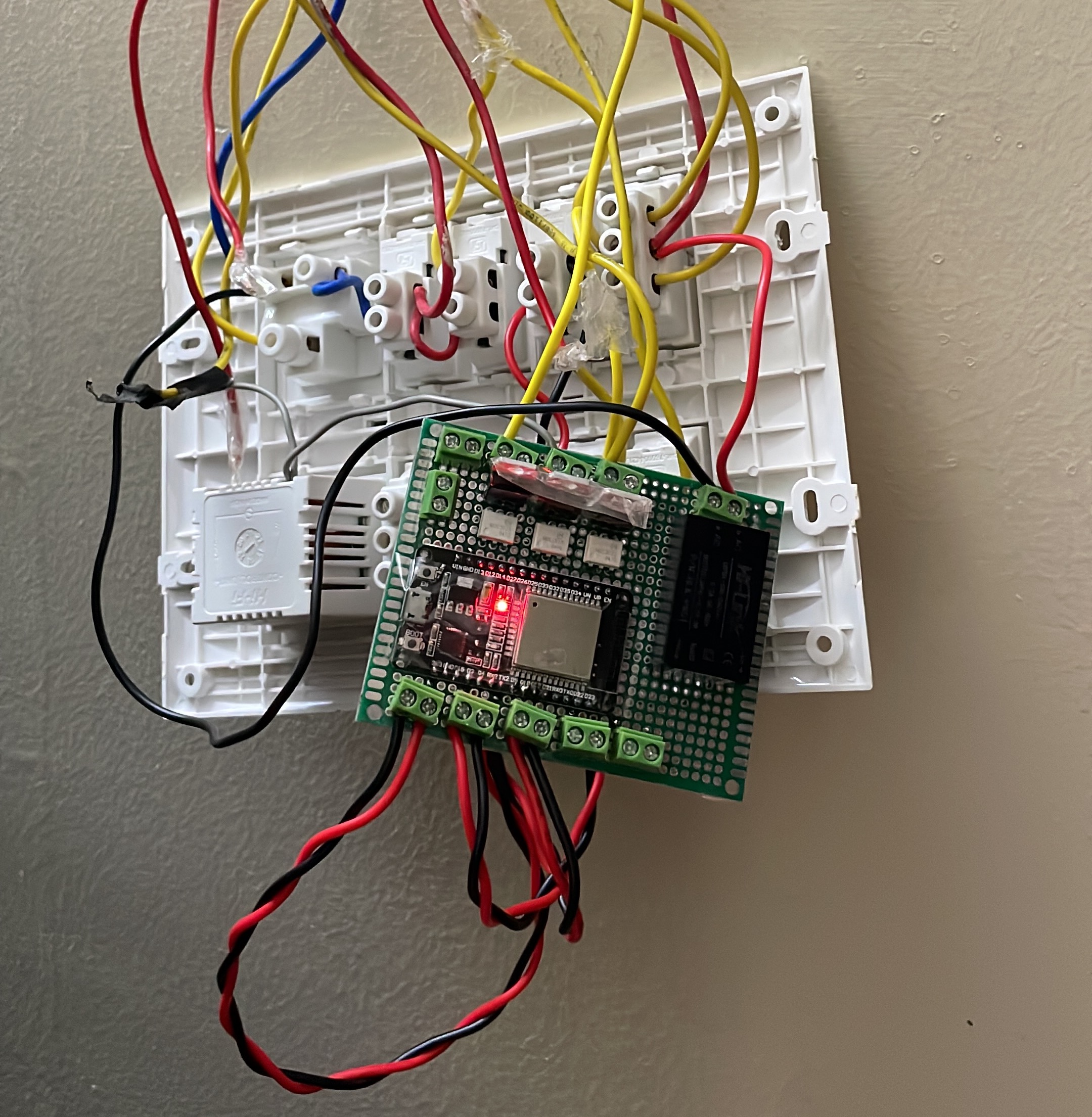
In-wall connections
Iteration #2
Iteration #1 design proved to be good and during the 3 months of operation, no hiccups were observed. It survived a lot of power failures and switching operations. The design was moved from perfboard to a custom designed PCB:
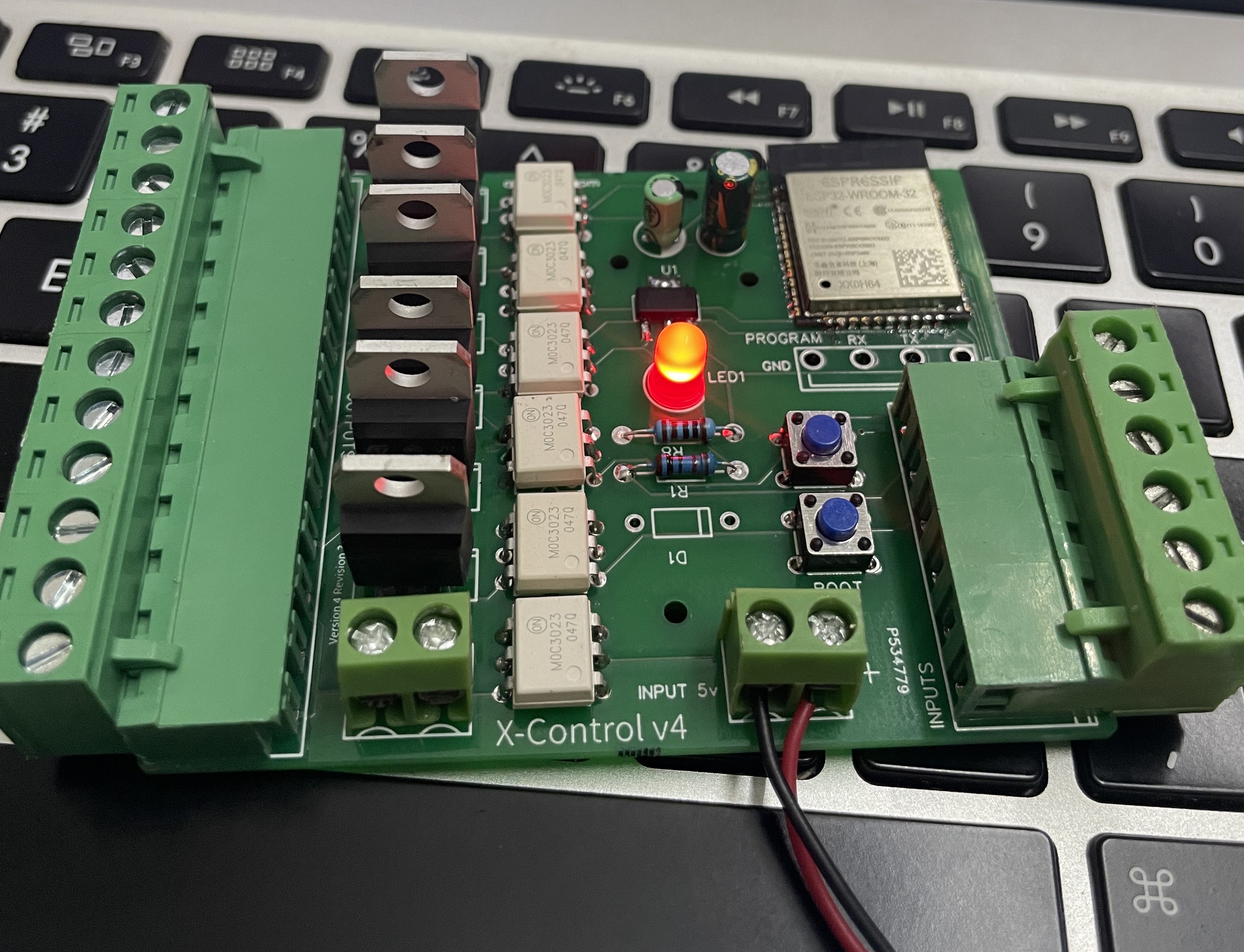
This design used an ESP32-WROOM32 module instead of the ESP32 dev kit. Also introduced a different type of connectors to further modularise the design.
One major issue with this design was the dimension - it would never fit inside a wall panel, it was a design iteration to test the trace widths & copper thickness needed to support higher loads anyway.
Iteration 3
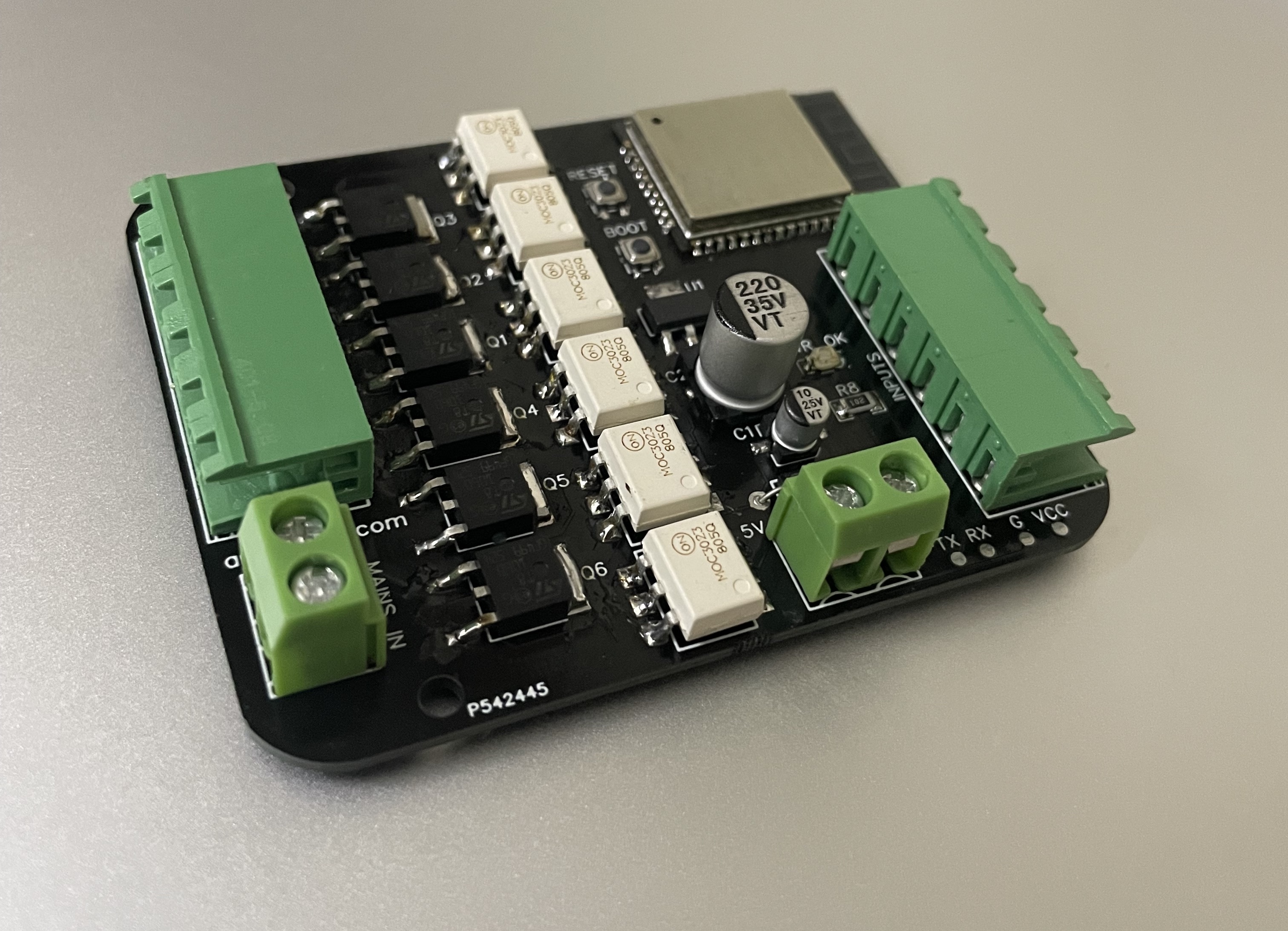
This version of the hardware fixed a few issues identified with Iteration #2, major one being the size. This hardware revision uses SMD components and the size was minimised to a credit card size. This fits perfectly within a switch panel.
My plan was to use a centrally provided 5V power to each of the wall modules and hence power supply was omitted from the board.
At this point, the hardware was finalised and started the testing of this revision within a wall panel(please excuse the mess of wires!):
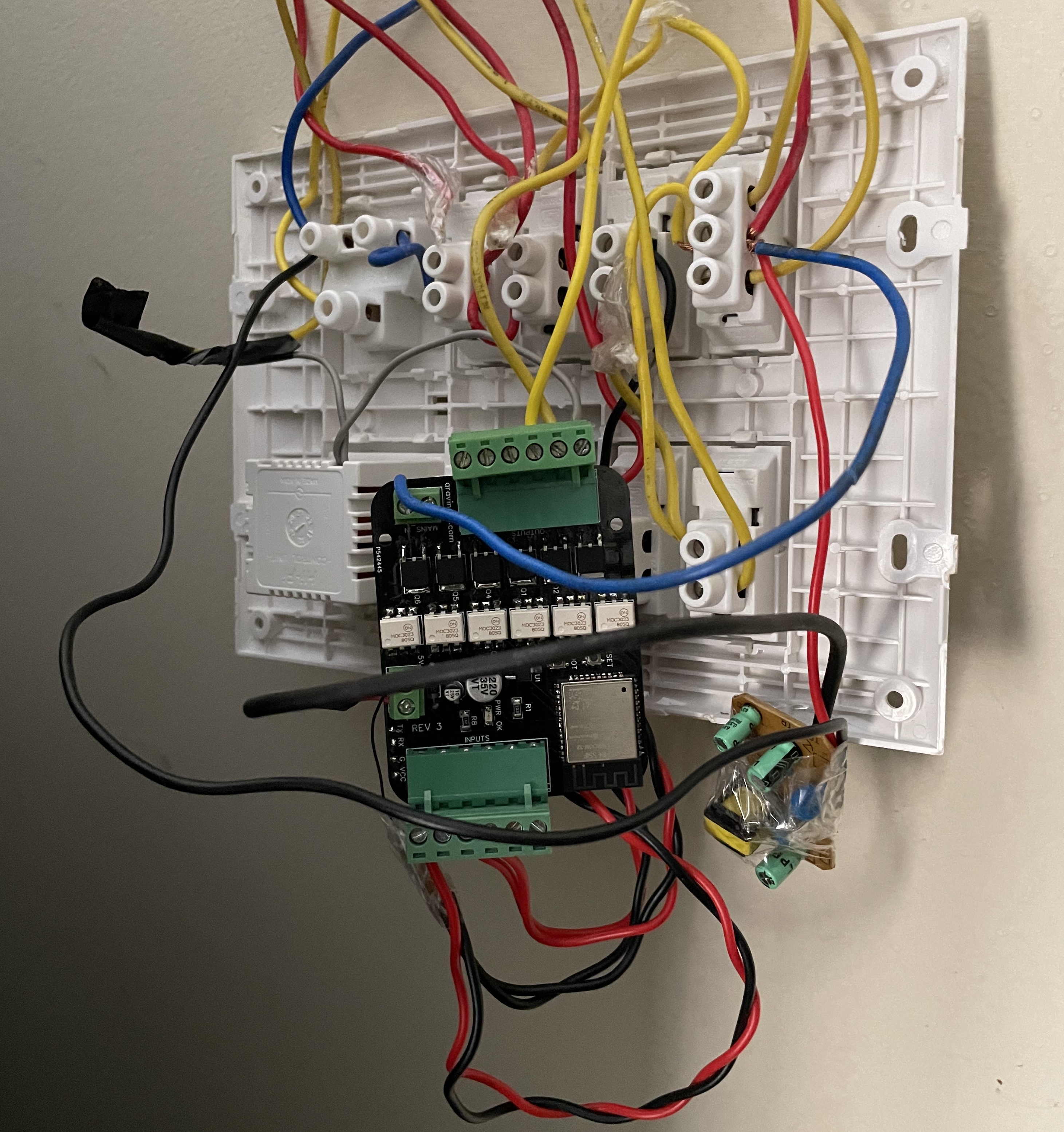
The external 5v powersupply is visible in the above photo.
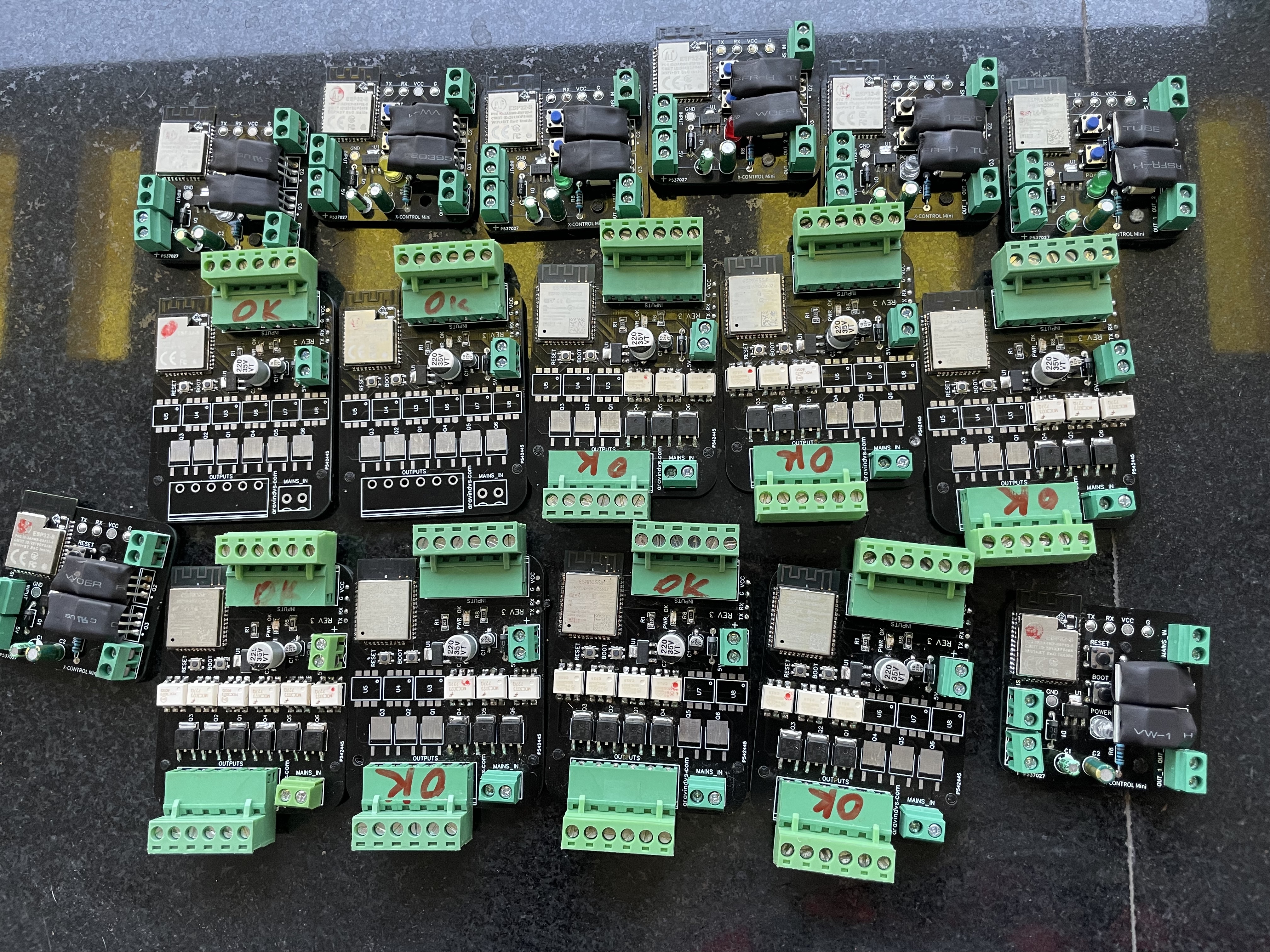
This was a very functional design and final few touches were made to the PCB. The finalised version was then given to the PCB manufacturer and a bulk of them were produced & assembled.
I ended up creating 2 versions of the module - original one with 6 I/O and a second version with 2 I/Os to be put within smaller wall panels. Below photograph shows the fully assembed & tested units ready to be installed:
This pretty much completes the hardware part of the implementation.
Next part of this series will describe how the module was installed, issues found along the way and software setup part.
Thanks for reading!