Recent visit to Ikea made me buy a bunch of their cute little things, the Vindriktning was one of them. Its a very simple air quality monitor that measures the PM2.5 particles in the air and shows an LED indicator based on the concentration in µg/m³ it reads.
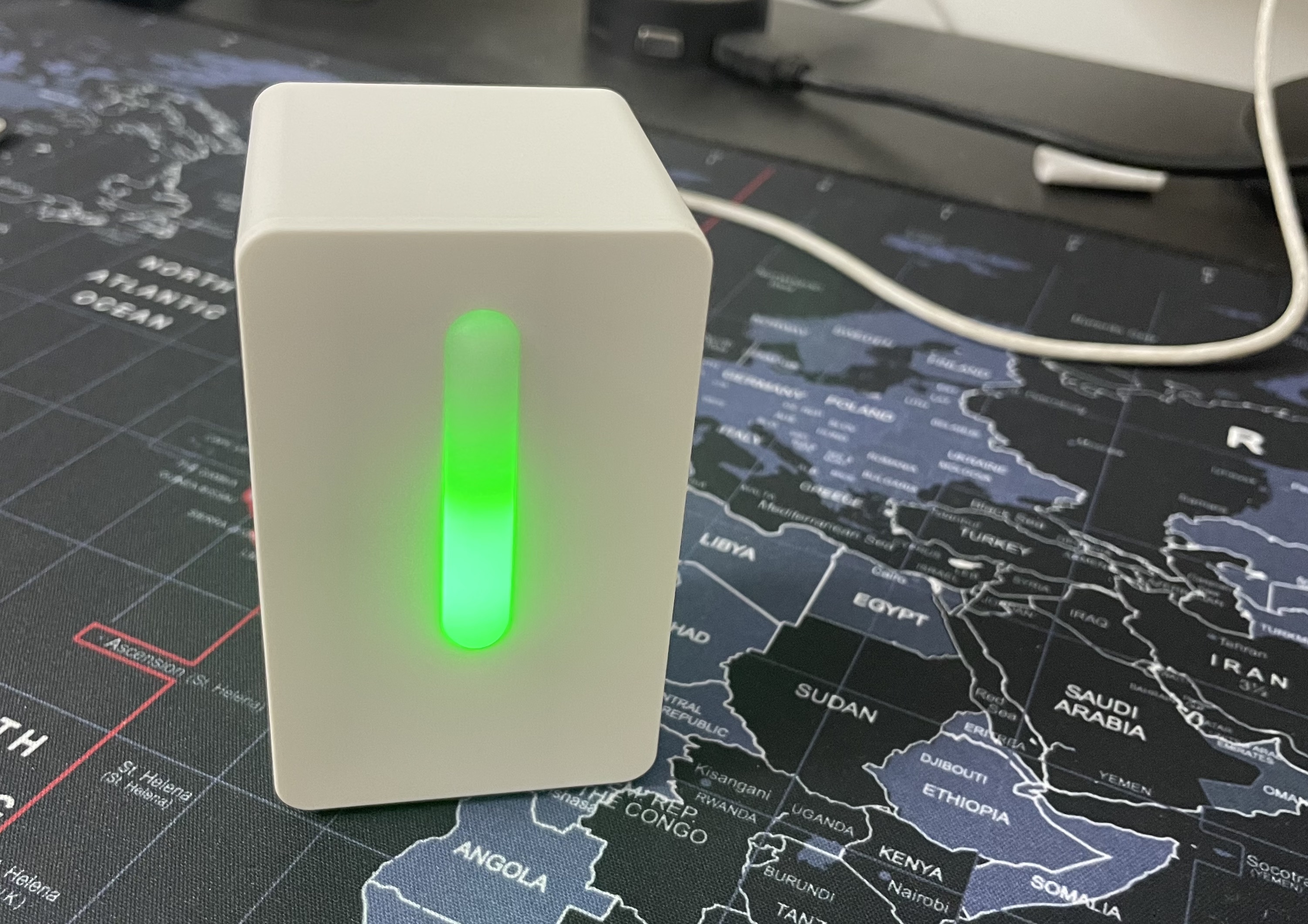
The PM2.5 reading to light conversion is done based on the following table, which is taken from their product manual:
| PM2.5 Concentration(µg/m³) | LED Color |
|---|---|
| 0-35 | Green (Good) |
| 36-85 | Amber (Ok) |
| 86+ | Red (Not Good) |
The sensor is very cheap at around ₹1000(around $12) and the design is pretty good as well, it kind of blends in with the decor around.
I had the sensor as-is for a day, I took it apart to see what makes it click the next day. The unit has a PM2.5 sensor with a fan that blows air directly through the sensor. There is a PCB with a micro controller controlling the operations. The sensor has a lot of free space inside it & a quick look around revealed that this sensor has been converted into a Smart Sensor by a number of people and Tasmota fully supports this. Converting the sensor as a smart sensor is pretty straight forward - just add an ESP8266 with Tasmota firmware & configure the pins, pretty easy. I’ve used the Wemos D1 Mini board for this, its an ESP8266 based development board thats small enough to fit inside the sensor housing.
Hardware
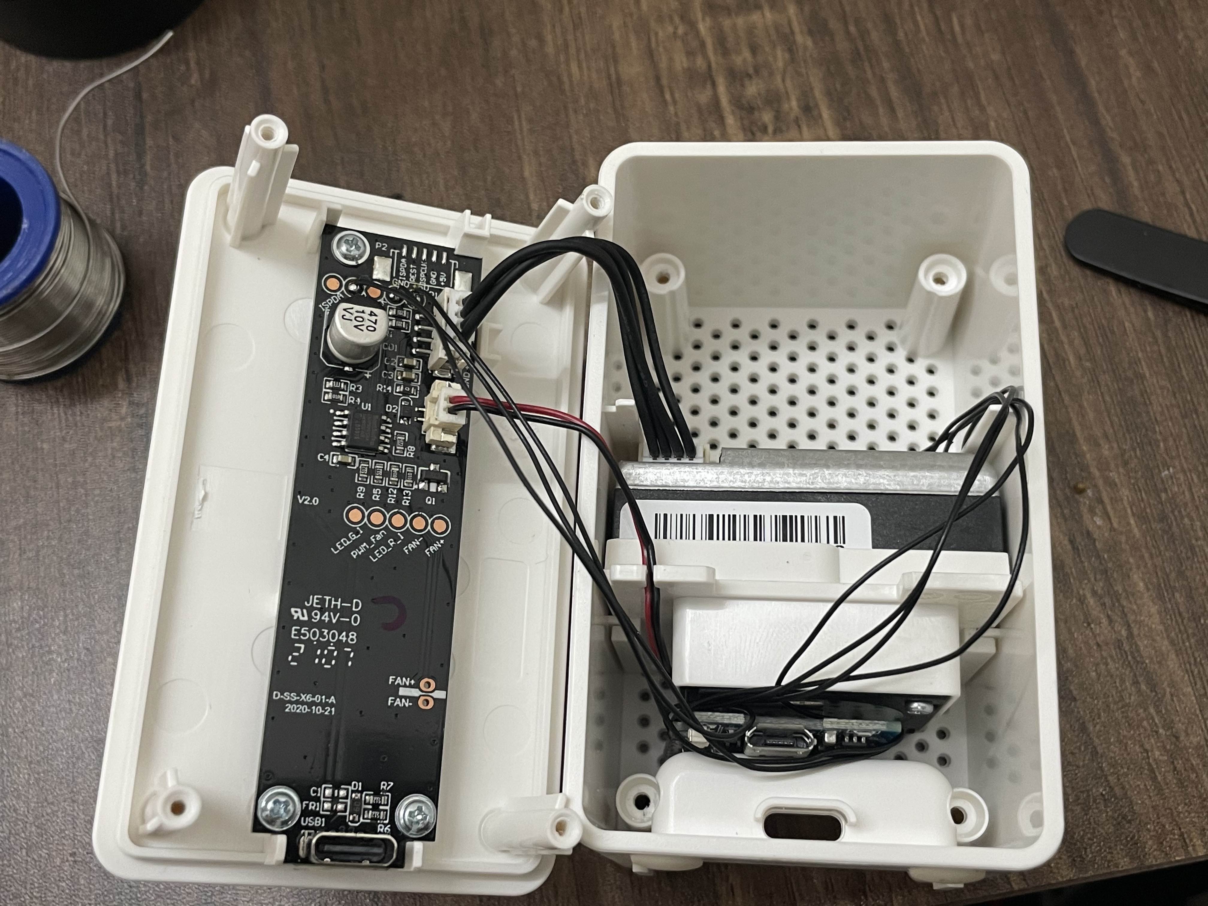
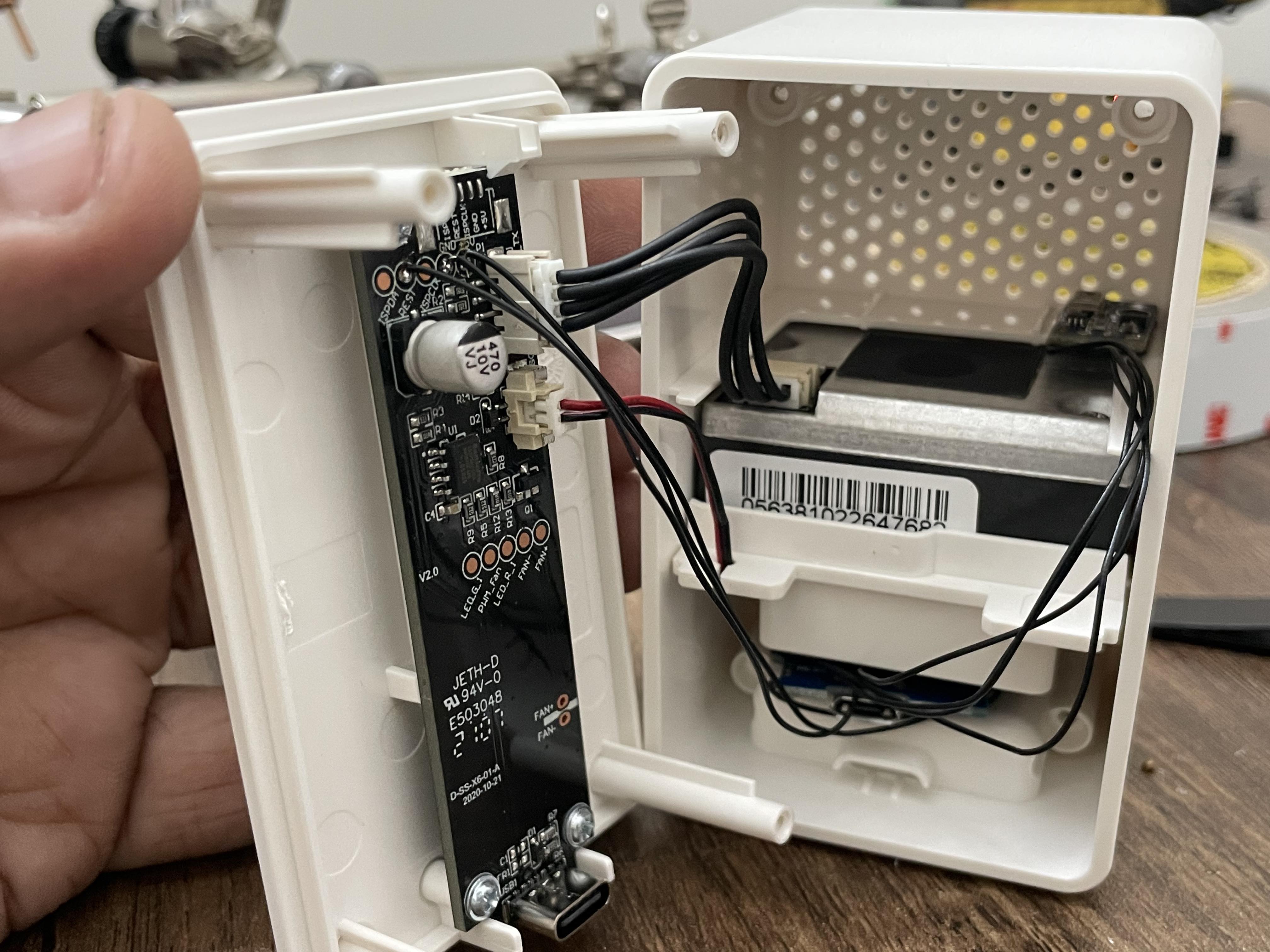
If we’re going to transform it into a “Smart Sensor”, why not add an additional sensor as well? A temperature sensor maybe? Thats exactly what I did, added an AHT10 temperature & humidity sensor I had lying around. The original PCB is a well designed and has a bunch of PCB pads & testing points that are labelled, looks like Ikea knew that people will be taking this thing apart!
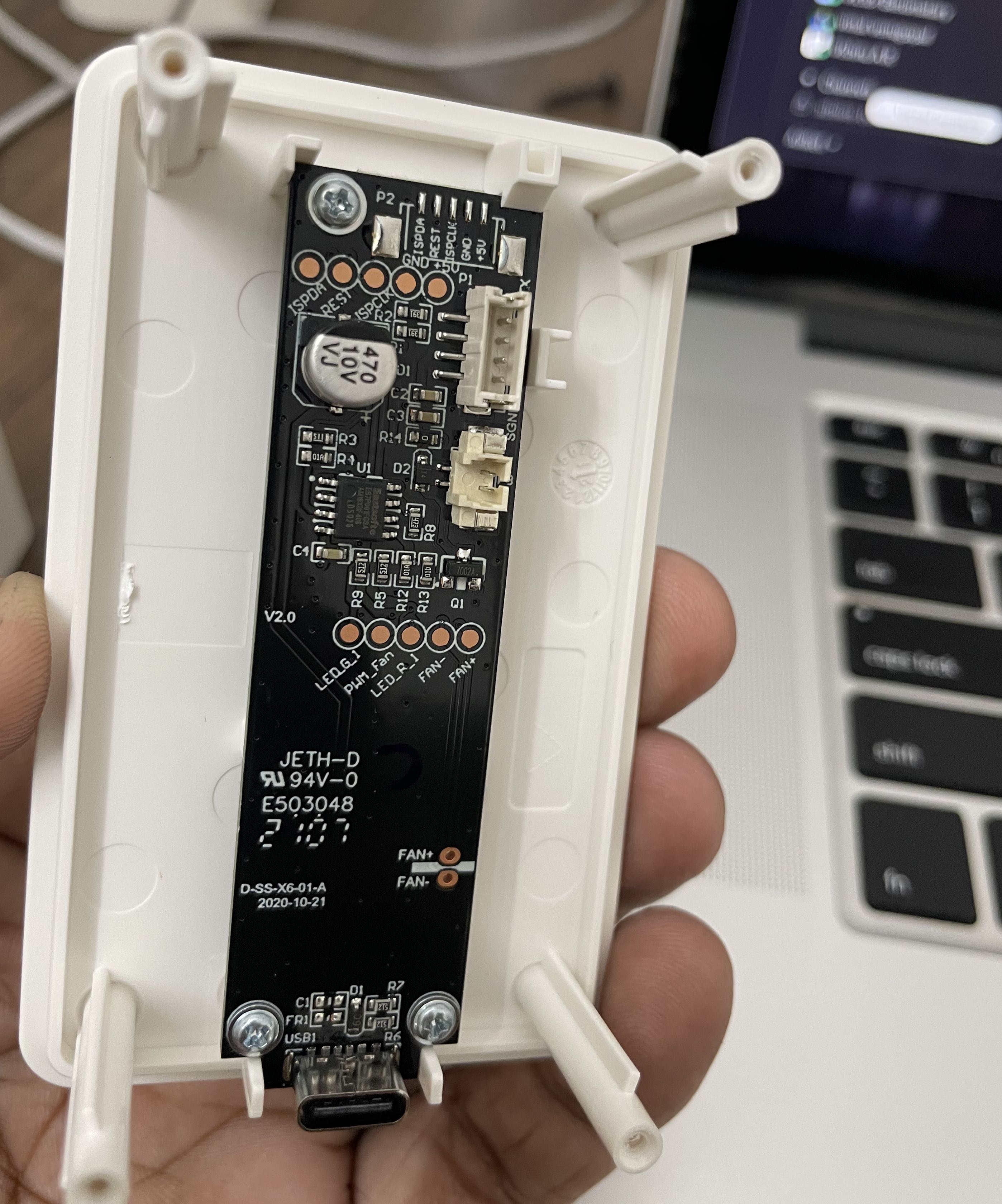
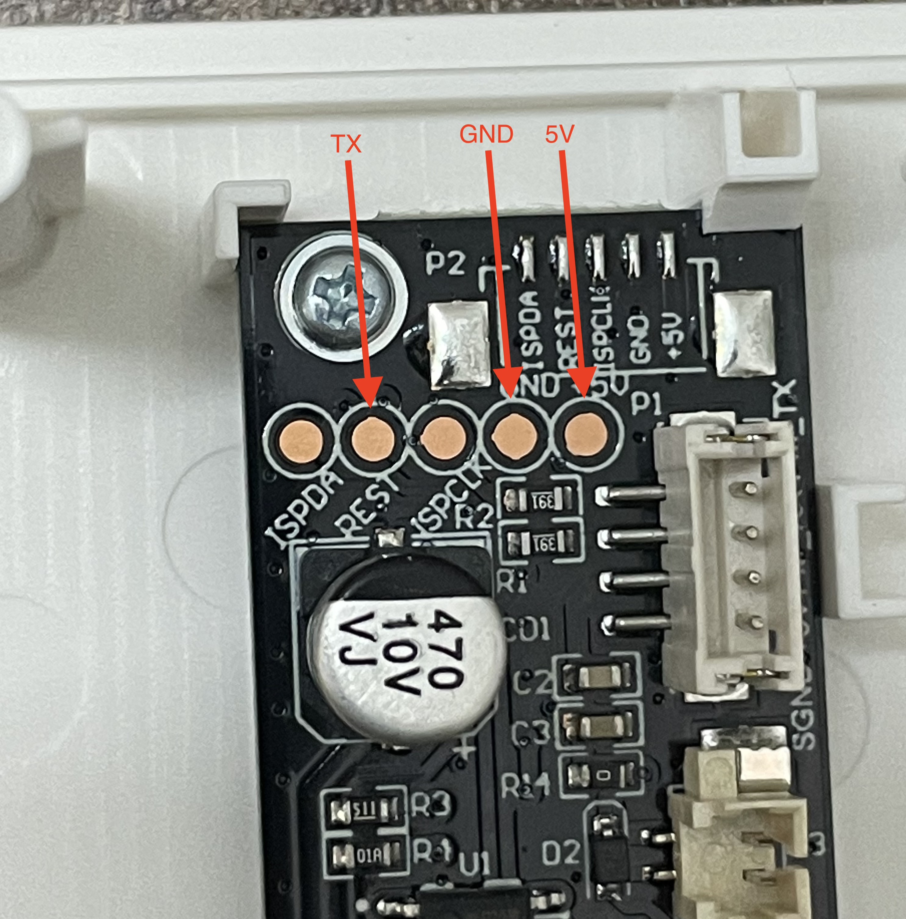
Since there are well labelled pads available, we can simply use them instead of making ugly solder joints on the pins of components/sockets, below are the pads that we’re interested in:
| Pin | Description |
|---|---|
| GND | Ground |
| 5v | VCC |
| REST | PM2.5 Sensor UART TX |
The following Pin mapping is made with the sensor PCB, the Wemos D1 Mini & AHT10 temperature humidity sensor module:
| Sensor Pin | Wemos D1 Mini Pin |
|---|---|
| Vindriktning REST | D5(GPIO14) |
| Vindriktning 5V | 5v |
| Vindriktning GND | GND |
| AHT10 GND | GND |
| AHT10 VCC | 3.3v |
| AHT10 SDA | D7 (GPIO13) |
| AHT10 SCL | D6 (GPIO12) |
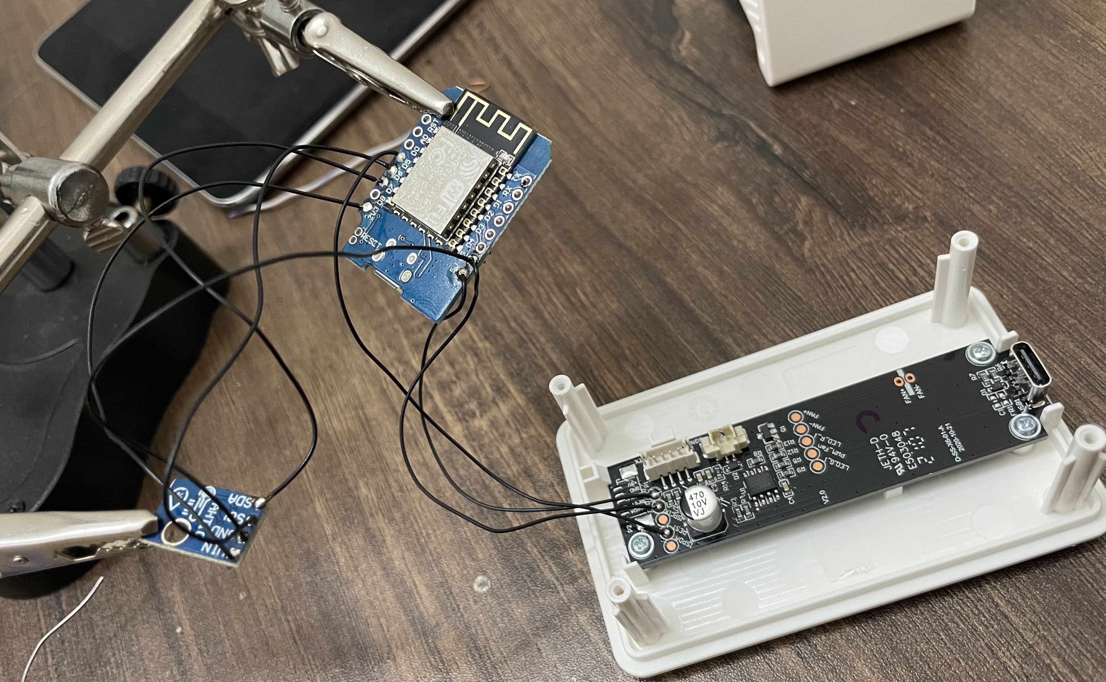
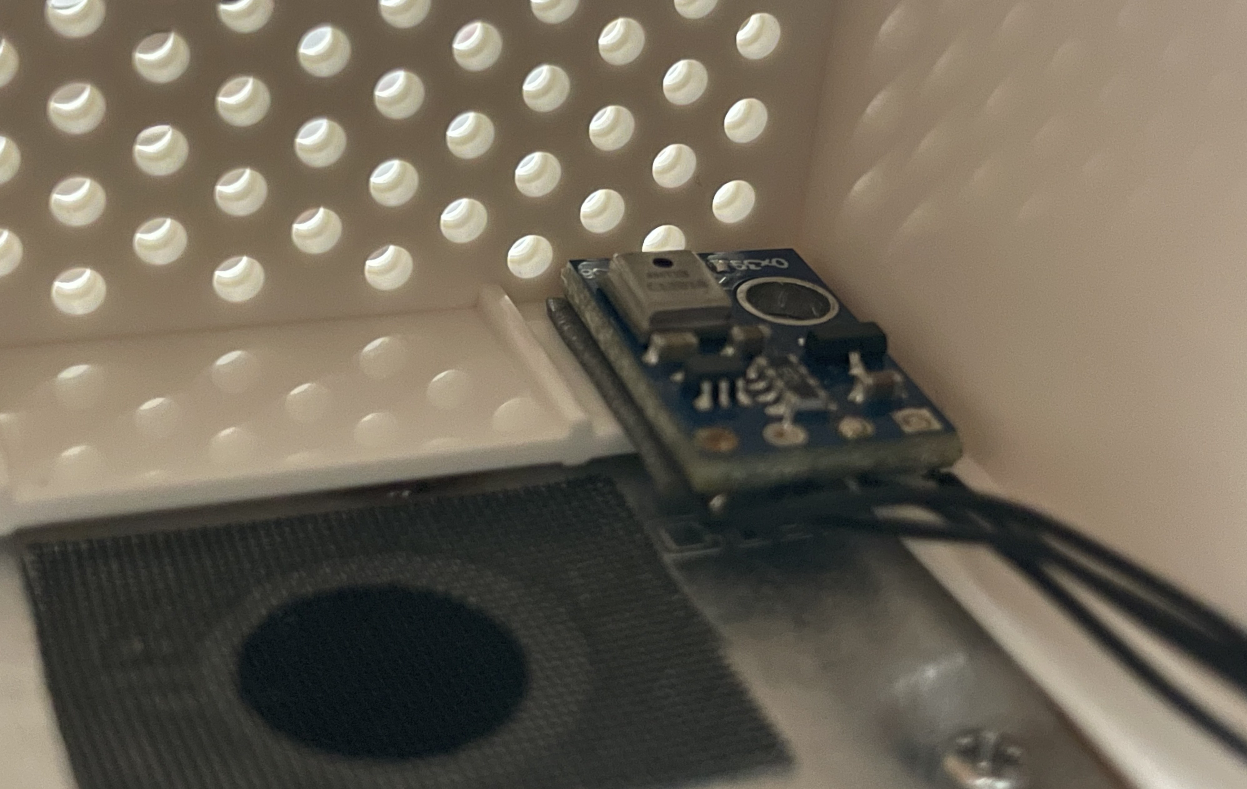
Once all connections were made, the AHT10 sensor was mounted on top directly in the airflow path with double sided tape as seen in the photo below:
Once the AHT10 sensor was mounted, the Wemos D1 was pushed into the gap between fan and the bottom of the sensor case, since the fan was closed at the bottom, it was was an easy affair:
Software
Tasmota web installer was used to install Tasmota onto the Wemos D1 Mini: https://tasmota.github.io/install/
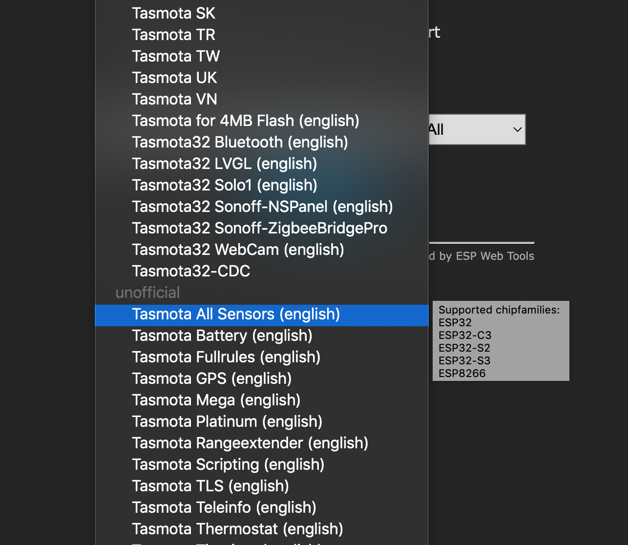
Software side of things are pretty straight forward - the only caveat here is to flash the All Sensors version of Tasmota and not the base version. This can be done by choosing the Tasmota All Sensors from the drop down menu on the web installer:
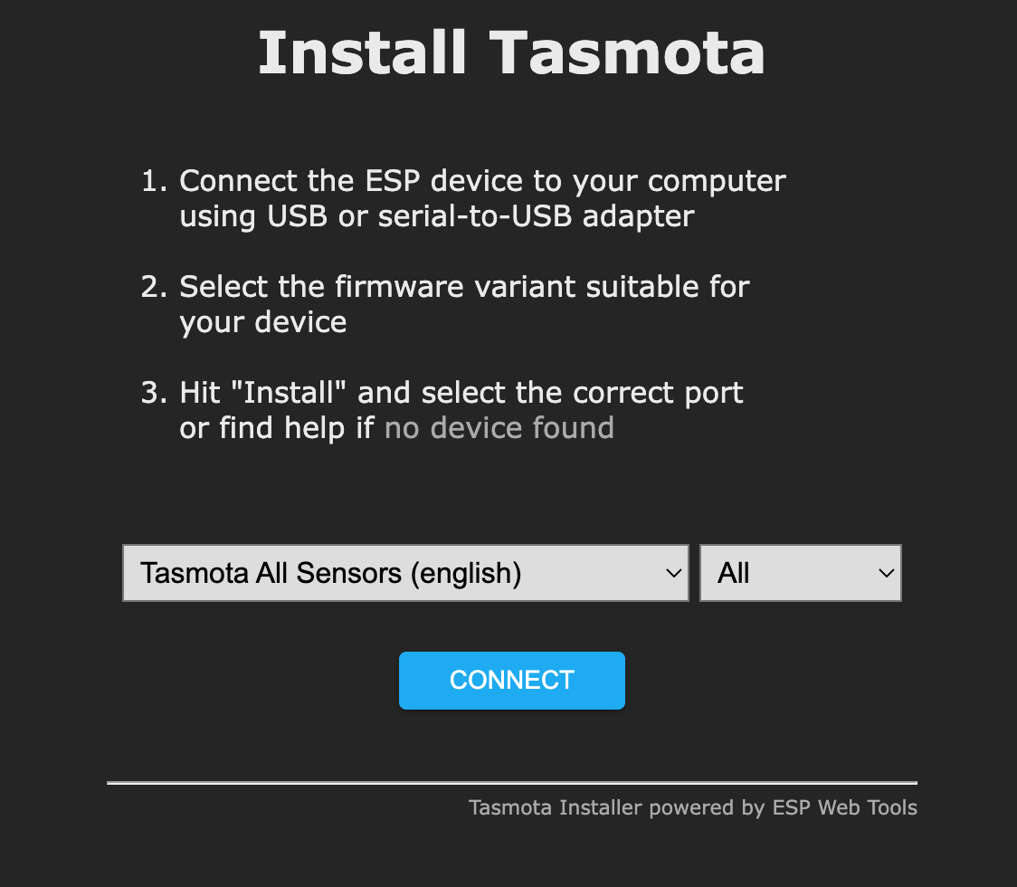
Click on connect & then install (Make sure to check Erase Device) and once installed, configure wifi and login to the Tasmota device to configure it,
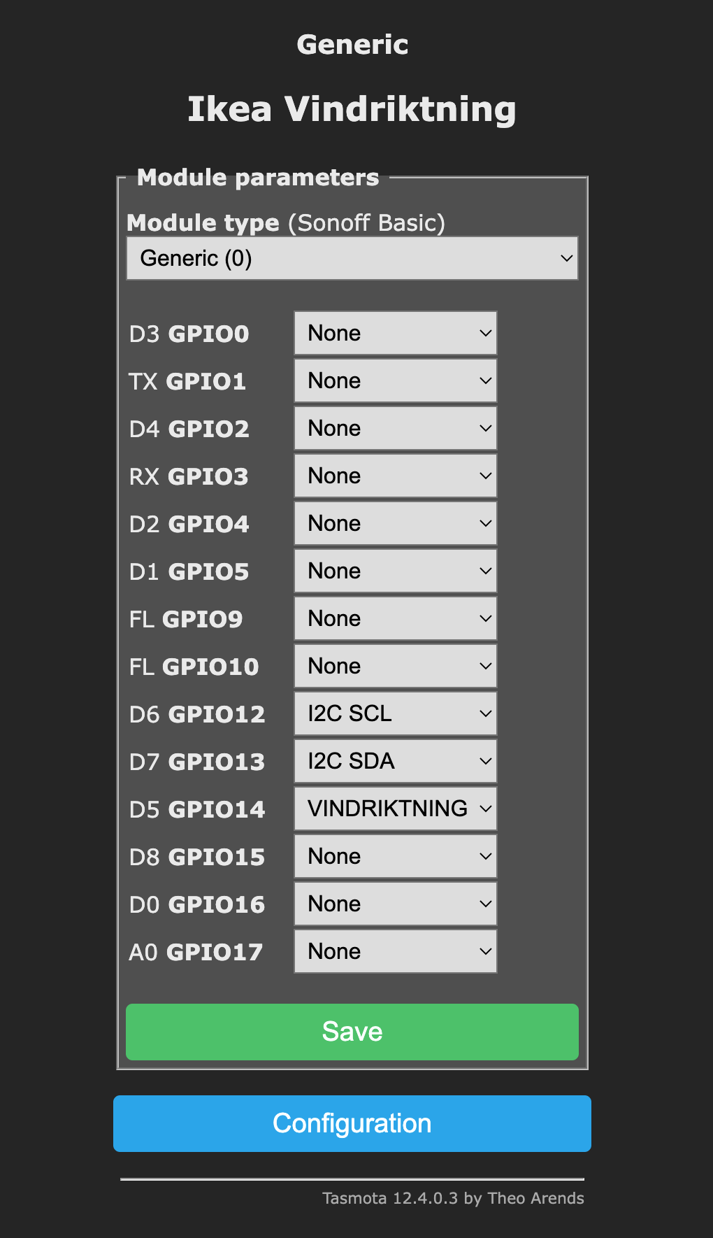
- Login to the Tasmota dashboard of the device
- Configuration > Configure Module
- Select “Module Type” as
Generic(0)& click on Save, the device will reboot - Once available, go to Configuration > Configure Module and select the correct Pin mappings and you’re done!
Once you configure I2C details for the AHT10 sensor, Tasmota will read the sensor as a UV Sensor initially because of an address conflict, to handle it, you need to tell Tasmota to disable the UV sensor driver & enable the AHTx sensor driver, you can do that by going into the Tasmota Console of the device and running the following commands:
I2CDriver12 0
I2CDriver43 1
I2CDriver12 is the driver for VEML6070 UV sensor & I2CDriver43 is the driver for our AHT10 sensor. Details on all available I2C drivers here: https://tasmota.github.io/docs/I2CDEVICES/#supported-i2c-devices
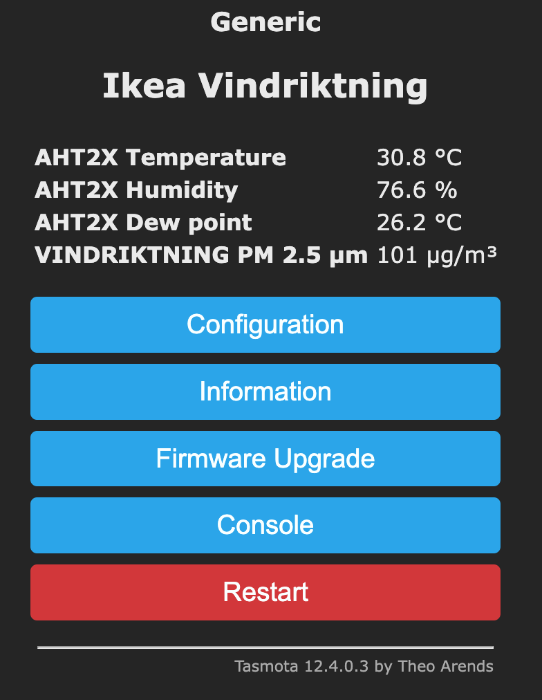
Tasmota will restart after saving and you should be able to see the sensor readings on screen, I’ve named my Tasmota sensor as Ikea Vindriktning:
Home Assistant Setup
Home Assistant setup is pretty straight forward, configure MQTT server details in the sensor and Home Assistant will pick it up automatically:
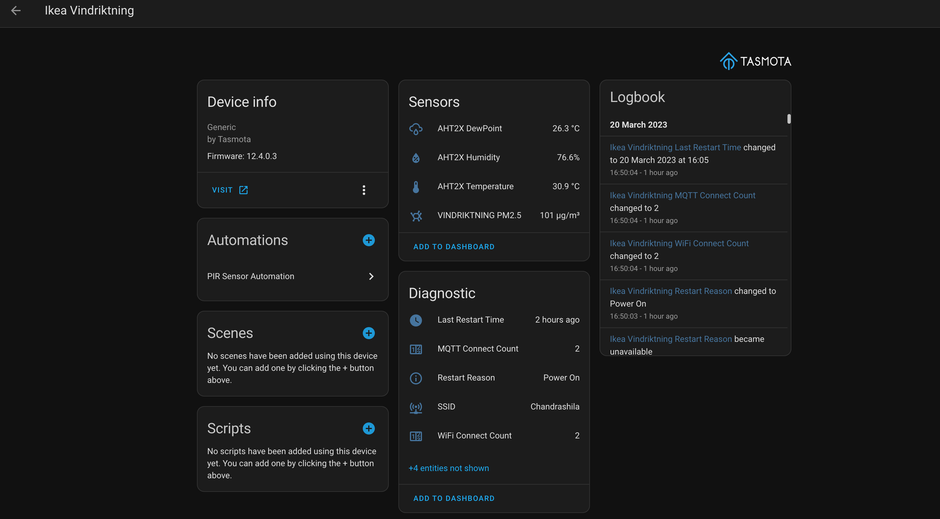
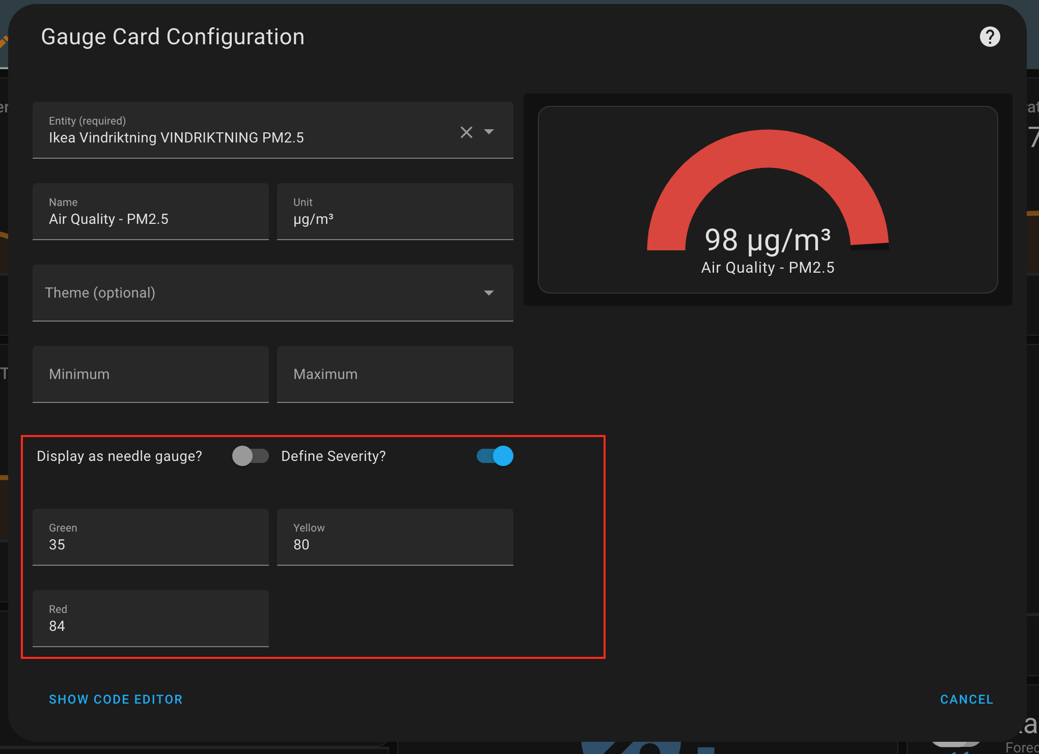
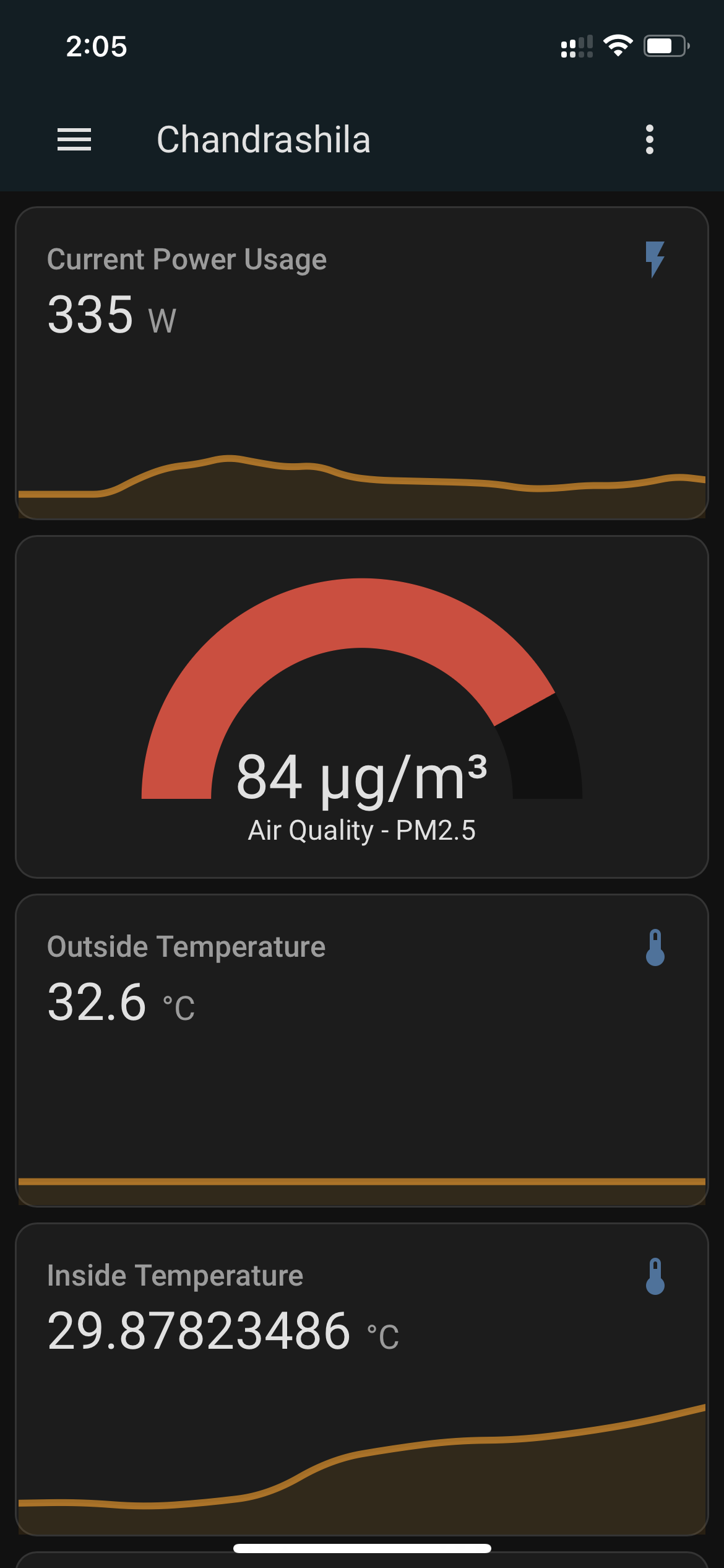
Sensor card added to dashboard with color preset configuration to match the light on the sensor itself:
Conclusion
Pretty happy with the outcome, I’m already planning on getting more units to do the conversion.